- 您现在的位置:买卖IC网 > Sheet目录3873 > PIC18F45K20-I/MV (Microchip Technology)MCU 32KB FLASH 1536B RAM 40-UQFN
2010 Microchip Technology Inc.
DS41303G-page 31
PIC18F2XK20/4XK20
2.4.3
LP, XT, HS MODES
The LP, XT and HS modes support the use of quartz
crystal resonators or ceramic resonators connected to
OSC1 and OSC2 (Figure 2-3). The mode selects a low,
medium or high gain setting of the internal inverter-
amplifier to support various resonator types and speed.
LP Oscillator mode selects the lowest gain setting of the
internal inverter-amplifier. LP mode current consumption
is the least of the three modes. This mode is best suited
to drive resonators with a low drive level specification, for
example, tuning fork type crystals.
XT Oscillator mode selects the intermediate gain
setting of the internal inverter-amplifier. XT mode
current consumption is the medium of the three modes.
This mode is best suited to drive resonators with a
medium drive level specification.
HS Oscillator mode selects the highest gain setting of the
internal inverter-amplifier. HS mode current consumption
is the highest of the three modes. This mode is best
suited for resonators that require a high drive setting.
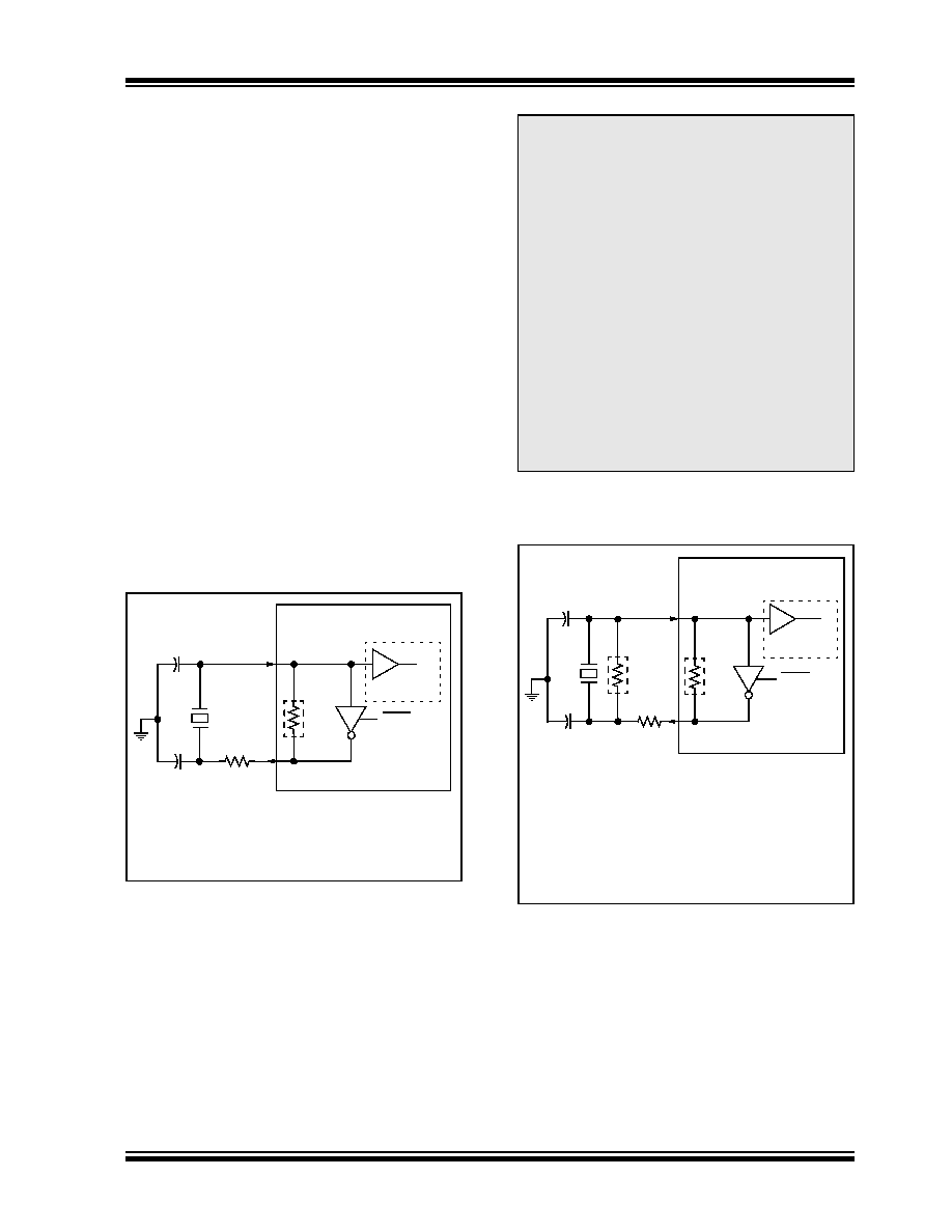
Figure 2-3 and Figure 2-4 show typical circuits for
quartz crystal and ceramic resonators, respectively.
FIGURE 2-3:
QUARTZ CRYSTAL
OPERATION (LP, XT OR
HS MODE)
FIGURE 2-4:
CERAMIC RESONATOR
OPERATION
(XT OR HS MODE)
Note 1:
A series resistor (RS) may be required for
quartz crystals with low drive level.
2:
The value of RF varies with the Oscillator mode
selected (typically between 2 M
to 10 M.
C1
C2
Quartz
RS(1)
OSC1/CLKIN
RF(2)
Sleep
To Internal
Logic
PIC MCU
Crystal
OSC2/CLKOUT
Note 1: Quartz crystal characteristics vary according
to type, package and manufacturer. The
user should consult the manufacturer data
sheets for specifications and recommended
application.
2: Always verify oscillator performance over
the VDD and temperature range that is
expected for the application.
3: For oscillator design assistance, reference
the following Microchip Applications Notes:
AN826, “Crystal Oscillator Basics and
Crystal Selection for rfPIC and PIC
Devices” (DS00826)
AN849, “Basic PIC Oscillator Design”
(DS00849)
AN943, “Practical PIC Oscillator
Analysis and Design” (DS00943)
AN949, “Making Your Oscillator Work”
(DS00949)
Note
1: A series resistor (RS) may be required for
ceramic resonators with low drive level.
2: The value of RF varies with the Oscillator mode
selected (typically between 2 M
to 10 M.
3: An additional parallel feedback resistor (RP)
may be required for proper ceramic resonator
operation.
C1
C2 Ceramic
RS(1)
OSC1/CLKIN
RF(2)
Sleep
To Internal
Logic
PIC MCU
RP(3)
Resonator
OSC2/CLKOUT
发布紧急采购,3分钟左右您将得到回复。
相关PDF资料
PIC16CR76T-I/SS
IC PIC MCU 8KX14 28SSOP
PIC18F13K50-I/P
IC PIC MCU FLASH 4KX16 20-PDIP
PIC16CR76T-I/SO
IC PIC MCU 8KX14 28SOIC
PIC18LF24K22-I/MV
IC PIC MCU 16KB FLASH 28UQFN
PIC18LF24K22-I/ML
IC PIC MCU 16KB FLASH 28QFN
PIC16CR76T-I/ML
IC PIC MCU 8KX14 28QFN
PIC16F627-04/P
IC MCU FLASH 1KX14 COMP 18DIP
PIC18F45J10-I/ML
IC PIC MCU FLASH 16KX16 44QFN
相关代理商/技术参数
PIC18F45K20-I/P
功能描述:8位微控制器 -MCU 32KB Flash 1536B RAM 25 I/O 8B RoHS:否 制造商:Silicon Labs 核心:8051 处理器系列:C8051F39x 数据总线宽度:8 bit 最大时钟频率:50 MHz 程序存储器大小:16 KB 数据 RAM 大小:1 KB 片上 ADC:Yes 工作电源电压:1.8 V to 3.6 V 工作温度范围:- 40 C to + 105 C 封装 / 箱体:QFN-20 安装风格:SMD/SMT
PIC18F45K20-I/PT
功能描述:8位微控制器 -MCU 32KB Flash 1536B RAM 25 I/O 8B RoHS:否 制造商:Silicon Labs 核心:8051 处理器系列:C8051F39x 数据总线宽度:8 bit 最大时钟频率:50 MHz 程序存储器大小:16 KB 数据 RAM 大小:1 KB 片上 ADC:Yes 工作电源电压:1.8 V to 3.6 V 工作温度范围:- 40 C to + 105 C 封装 / 箱体:QFN-20 安装风格:SMD/SMT
PIC18F45K20T-I/ML
功能描述:8位微控制器 -MCU 32KB Flash 1536B RAM 25 I/O 8B RoHS:否 制造商:Silicon Labs 核心:8051 处理器系列:C8051F39x 数据总线宽度:8 bit 最大时钟频率:50 MHz 程序存储器大小:16 KB 数据 RAM 大小:1 KB 片上 ADC:Yes 工作电源电压:1.8 V to 3.6 V 工作温度范围:- 40 C to + 105 C 封装 / 箱体:QFN-20 安装风格:SMD/SMT
PIC18F45K20T-I/MLV01
制造商:Microchip Technology Inc 功能描述:
PIC18F45K20T-I/MV
功能描述:8位微控制器 -MCU 32KB FL 1536b RAM 8b Familynanowatt XLP
RoHS:否 制造商:Silicon Labs 核心:8051 处理器系列:C8051F39x 数据总线宽度:8 bit 最大时钟频率:50 MHz 程序存储器大小:16 KB 数据 RAM 大小:1 KB 片上 ADC:Yes 工作电源电压:1.8 V to 3.6 V 工作温度范围:- 40 C to + 105 C 封装 / 箱体:QFN-20 安装风格:SMD/SMT
PIC18F45K20T-I/PT
功能描述:8位微控制器 -MCU 32KB Flash 1536B RAM 25 I/O 8B RoHS:否 制造商:Silicon Labs 核心:8051 处理器系列:C8051F39x 数据总线宽度:8 bit 最大时钟频率:50 MHz 程序存储器大小:16 KB 数据 RAM 大小:1 KB 片上 ADC:Yes 工作电源电压:1.8 V to 3.6 V 工作温度范围:- 40 C to + 105 C 封装 / 箱体:QFN-20 安装风格:SMD/SMT
PIC18F45K22-E/ML
功能描述:8位微控制器 -MCU 32KB Flash 1536B RAM 8B nanoWatt RoHS:否 制造商:Silicon Labs 核心:8051 处理器系列:C8051F39x 数据总线宽度:8 bit 最大时钟频率:50 MHz 程序存储器大小:16 KB 数据 RAM 大小:1 KB 片上 ADC:Yes 工作电源电压:1.8 V to 3.6 V 工作温度范围:- 40 C to + 105 C 封装 / 箱体:QFN-20 安装风格:SMD/SMT
PIC18F45K22-E/MV
功能描述:8位微控制器 -MCU 32KB 1536b RAM 8bit familynanoWatt XLP RoHS:否 制造商:Silicon Labs 核心:8051 处理器系列:C8051F39x 数据总线宽度:8 bit 最大时钟频率:50 MHz 程序存储器大小:16 KB 数据 RAM 大小:1 KB 片上 ADC:Yes 工作电源电压:1.8 V to 3.6 V 工作温度范围:- 40 C to + 105 C 封装 / 箱体:QFN-20 安装风格:SMD/SMT